(1). 上圖為ModelSim模擬的結果,下圖為NC Verilog模擬的結果,一模一樣的Verilog code卻產生不同的結果。
(2). 主要是因為module的input輸入值,需要先宣告一個reg接受並且給予初始值。
module PureBus(
.....
input [2:0]Mode,
.....
);
reg [2:0]mode_set;
always@(posedge Clk or negedge Reset)
begin
if(!Reset)
begin
........
r_mode_set <= 0;
end
else
begin
.......
r_mode_set <= Mode;
end
end
endmodule
修改完成,再用NC Verilog模擬,結果就與ModelSim模擬的結果一樣。有使用Active HDL測試,發現Active HDL與NC Verilog模擬的結果是一樣的,Active HDL與NC Verilog相對於ModelSim對於電路初始值得要求比較嚴謹。
2018年12月23日 星期日
2018年12月21日 星期五
NC-Verilog(3) - 模擬
(1). 選擇"Tools" > "Elaborator..."。
(2). 勾選"Other Options",輸入"-timescale 1ns/1ns",設定模擬 的(單位)/(精度),設定完成按"OK"。
**如果所有的Verilog程式碼開頭都有加入"-timescale 1ns/1ns",可以省去此項步驟。
(3). 點選"testbench",再點選"Elaborator"。
(4). 點選"worklib.testbench.module",再點選"Simulator"。
(5). 開啟"SimVision"視窗。
(6). 點選"testbench",再點選"Send"。
(7). 開啟"Waveform"視窗,點選"Run"視窗執行並顯示模擬結果。
NC-Verilog(2) - 執行NCLaunch與編譯
(2). 點選"Multiple Step"。
(3). 點選"...",選擇上個章節Verilog的程式路徑,之後按"OK"。
(4). 新的專案要建立Library,點選"Yes"。
(5). 點選"OK"。
(6). 點選"OK"。
(7). 點選需要編譯的Verilog程式,再點選"Verilog compiler",開始編譯。
NC-Verilog(1) - 硬體描述語言撰寫
NC-Verilog下的三個工具:
ncvlog (Compiles the Verilog source files.)
ncelab (Elaborates the design and generates a simulation snapshot.)
ncsim (Simulates the snapshot.)
(1). 先產生Verilog程式,如下所示。
/////////////////////////////Schematic
module Test(a, b, c, d, En, Sel, f);
input a, b, c, d, En, Sel;
output f;
wire f;
wire g, h, i, j;
assign g = a | b;
assign i = g & En;
assign h = c | d;
assign j = h & En;
assign f = (Sel==1'b0) ? i : j;
endmodule
/////////////////////////////Testbench
module testbench;
reg a, b, c, d, En, Sel;
wire f;
Test UUT(
.a(a),
.b(b),
.c(c),
.d(d),
.En(En),
.Sel(Sel),
.f(f) );
initial
begin
a = 1'b0; // Time = 0
b = 1'b1;
c = 1'b0;
d = 1'b1;
En = 1'b0;
Sel = 1'b0;
#20; // Time = 20
a = 1'b1;
#10; // Time = 30
b = 1'b0;
c = 1'b1;
#10; // Time = 40
a = 1'b0;
#10; // Time = 50
En = 1'b1;
#10; // Time = 60
c = 1'b0;
#10; // Time = 70
a = 1'b1;
d = 1'b0;
#20; // Time = 90
c = 1'b1;
#20; // Time = 110
a = 1'b0;
#10; // Time = 120
a = 1'b1;
#10; // Time = 130
c = 1'b0;
Sel= 1'b1;
#10; // Time = 140
a = 1'b0;
#30; // Time = 170
a = 1'b1;
#10; // Time = 180
c = 1'b1;
#20; // Time = 200
a = 1'b0;
end
endmodule
(2). 在Linux作業系統中建立一個目錄,並將Schematic與Testbench,複製至目錄中。
ncvlog (Compiles the Verilog source files.)
ncelab (Elaborates the design and generates a simulation snapshot.)
ncsim (Simulates the snapshot.)
/////////////////////////////Schematic
module Test(a, b, c, d, En, Sel, f);
input a, b, c, d, En, Sel;
output f;
wire f;
wire g, h, i, j;
assign g = a | b;
assign i = g & En;
assign h = c | d;
assign j = h & En;
assign f = (Sel==1'b0) ? i : j;
endmodule
/////////////////////////////Testbench
module testbench;
reg a, b, c, d, En, Sel;
wire f;
Test UUT(
.a(a),
.b(b),
.c(c),
.d(d),
.En(En),
.Sel(Sel),
.f(f) );
initial
begin
a = 1'b0; // Time = 0
b = 1'b1;
c = 1'b0;
d = 1'b1;
En = 1'b0;
Sel = 1'b0;
#20; // Time = 20
a = 1'b1;
#10; // Time = 30
b = 1'b0;
c = 1'b1;
#10; // Time = 40
a = 1'b0;
#10; // Time = 50
En = 1'b1;
#10; // Time = 60
c = 1'b0;
#10; // Time = 70
a = 1'b1;
d = 1'b0;
#20; // Time = 90
c = 1'b1;
#20; // Time = 110
a = 1'b0;
#10; // Time = 120
a = 1'b1;
#10; // Time = 130
c = 1'b0;
Sel= 1'b1;
#10; // Time = 140
a = 1'b0;
#30; // Time = 170
a = 1'b1;
#10; // Time = 180
c = 1'b1;
#20; // Time = 200
a = 1'b0;
end
endmodule
(2). 在Linux作業系統中建立一個目錄,並將Schematic與Testbench,複製至目錄中。
2018年11月30日 星期五
Allegro電路板設計 - Layout時更新元件庫
(1). 先檢查Database,選擇"Tools" > "Database Check..."。
(2). 勾選"Update all DRC(including Batch)"與"Check shape outlines",按"Check",之後會產生一個報表,請檢查是否有錯誤。
(3). 更新元件庫,點選"Place" > "Update Symbols..."。
(4). 在Select definitions for update:中勾選元件庫路徑,再勾選"Update symbol padstacks",按"Refresh",更新元件庫。
2018年11月26日 星期一
Allegro電路板設計 - Via、Pad加入與刪除淚滴(Teardrop)
增加Teardrop主要是避免信號線的線寬突然變小而造成Crosstalk現象。
(1). 點選"Route" > "Gloss" > "Parameters..."。
(2). 點選"Fillet and tapered trace"左邊按鍵。
(3). 確認"Circular pads''、"Pins''、"Vias''、"T connections''有勾選,之後按"OK"。
(4). 在"Fillet and tapered trace"對應的"Run"勾選,之後按"Gloss"。
(5). 結果顯示如下圖所示。
(6). 刪除Teardrop,選擇"Route" > "Gloss" > "Delete Fillet"。
(7). 使用"滑鼠左鍵"按住,並框選PCB。
(8). "滑鼠左鍵"放開後,即可刪除Teardrop。
2018年11月13日 星期二
鍵盤事件
(1). 點選"控制項"。
(2). 在屬性視窗中點選"事件按鈕(閃電圖示)"。
(3). 選擇"KeyDown"、"KeyPress"或"KeyUP"事件"快按兩下"。
a. KeyDown事件: 鍵盤任意鍵按住不放時觸發。
b. KeyPress事件: 鍵盤字元鍵被按時觸發。
c. KeyUP事件: 鍵盤任意鍵按下放開時觸發。
(4). 輸入程式。
KeyDown範例:
if(e.KeyCode == Keys.Enter)
{
...............
}
KeyPress範例:
if(e.KeyCode == (char)Keys.A)
{
...............
}
KeyUP範例:
if(e.KeyCode == Keys.Enter)
{
...............
}
(5). 在Form1.cs下點選視窗外框,將"KeyPreview"改成"True"。
注意:
KeyEventArgs類別的屬性: | |
Alt | 取得值,指出是否按下 ALT 鍵。 |
Control | 取得值,指出是否按下 CTRL 鍵。 |
Handled | 取得或設定值,指出是否處理事件。 |
KeyCode |
取得 KeyDown 或 KeyUp 事件的鍵盤程式碼。 |
KeyData |
取得 KeyDown 或 KeyUp 事件的按鍵資料。 |
KeyValue |
取得 KeyDown 或 KeyUp 事件的鍵盤值。 |
Modifiers | 取得 KeyDown 或 KeyUp 事件的輔助鍵旗標。 這些旗標是表示按下 CTRL、SHIFT 和 ALT 哪些按鍵組合。 |
Shift | 取得值,指出是否按下 SHIFT 鍵。 |
SuppressKeyPress |
取得或設定值,指出按鍵事件是否應該傳遞至基礎控制項。 |
Keys Enum(鍵盤列舉) | |
列舉常數值 | KeyCode |
Keys.D0~Keys.D9 | 48~57 |
Keys.A~Keys.Z | 65~90 |
Keys.F1~Keys.F12 | 112~121 |
Keys.Left~Keys.Right | 37、39 |
Keys.Up~Keys.Down | 38、40 |
Keys.Enter~Keys.Space | 13、32 |
Keys.ShiftKey | 16 |
Keys.ControlKey | 17 |
Keys.Escape | 27 |
2018年10月28日 星期日
Allegro電路板設計 - (12)Layout-輸出NC Drill Files、文字面、Gerber
產生文字面、輸出NC Drill Files、Gerber之前要先查看報表,看看設計是否有錯誤。
**快速檢查DRC操作流程**
輸出NC Drill Files:
步驟可以分為"NC Parameters"(鑽孔檔)、"NC Drill"。
(1). 選擇"Manufacture" > "NC" > "NC Parameters",開啟"NC Parameters"視窗。
(2). 勾選"Enhanced Excellon format",按下"Close",關閉"NC Parameters"視窗。
(3). 選擇"Manufacture" > "NC" > "NC Drill",開啟"NC Drill"視窗。
(4). 勾選"Auto tool select,"按下"Drill"按鍵。
(5). 輸出結果如下圖所示。
*如果電路中有使用到異形鑽孔(非圓形的鑽孔),需要再產生.rou檔。
產生文字面:
(1). 選擇"Manufacture" > "Silkscreen...",開啟"Auto Silkscreen"視窗。
(2).
Layer區塊:
勾選Both。
Classes and subclasses區塊:
Component value: None。
Device type: None。
Text區塊:
取消勾選 180
取消勾選 270
取消勾選 Allow under components(允許在元件下方)
勾選Lock autosilk text for incremental updates(鎖定增加更新autosilk文字)
設定完成按"Silkscreen",產生文字面。
輸出Gerber:
(1). 選擇"Manufacture" > "Artwork...",開啟"Artwork Control Form"視窗。
(2). 點選"General Parameters"標籤頁,
"Device type"群組:
勾選"Gerber RS274X"
"Format"群組:
Integer places: "3"
Decimal places: "5"(表示Millmeters小數點兩位)
"Output units"群組:
勾選"Millmeters"(輸出單位為公制)
(3). 點選"Film Control"標籤頁,
點選"Available films"群組內增加Gerber需要輸出的檔案夾,使用"滑鼠左鍵"點選BOTTOM或TOP檔案夾,再按"滑鼠右鍵" > "Add",
勾選"OUTLINE",之後按"OK"增加物件。
增加結果如下所示。
使用"滑鼠左鍵"點選BOTTOM或TOP檔案夾,再按"滑鼠右鍵" > "Display for Visibility",複製目前檔案夾的內容,
再選擇"Add",增加檔案夾,
輸入檔案夾名稱後,按"OK",
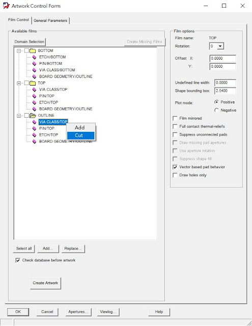
使用"滑鼠左鍵"點選新增檔案夾內的物件,按"Cut",刪除物件,再依照下述所列依序增加物件,
-TOP
+ETCH/TOP
+PIN/TOP
+VIA CLASS/TOP
+BOARD GEOMETRY/OUTLINE
-BOTTOM
+ETCH/BOTTOM
+PIN/BOTTOM
+VIA CLASS/BOTTOM
+BOARD GEOMETRY/OUTLINE
*********************************四層板內層加入
+BOARD GEOMETRY/OUTLINE
+BOARD GEOMETRY/SILKSCREEN_TOP
(6). 產生的檔案如下的所示。
(1). 點選"Drc Updata"的ICON,更新DRC檢查資料。
(2). 點選"Display" > "Status..."。
(3). 檢查Status視窗中,Symbols and nets與Shapes中是否有錯誤,如有顯示紅、黃色錯誤請修正,之後再執行步驟(1)、(2)、(3)。
輸出NC Drill Files:
步驟可以分為"NC Parameters"(鑽孔檔)、"NC Drill"。
(1). 選擇"Manufacture" > "NC" > "NC Parameters",開啟"NC Parameters"視窗。
(2). 勾選"Enhanced Excellon format",按下"Close",關閉"NC Parameters"視窗。
*如果產生鑽孔檔發生"The number of integer places specified for the drill output data is not enough for this design."的錯誤訊息,將Format: 2 . 5的 2 改成 3,就可以正確產生鑽孔檔。
(4). 勾選"Auto tool select,"按下"Drill"按鍵。
(5). 輸出結果如下圖所示。
(7). 按下"Route"按鍵。
產生文字面:
(1). 選擇"Manufacture" > "Silkscreen...",開啟"Auto Silkscreen"視窗。
(2).
Layer區塊:
勾選Both。
Classes and subclasses區塊:
Component value: None。
Device type: None。
Tolerance: None。
User part number: None。
Text區塊:
取消勾選 180
取消勾選 270
取消勾選 Allow under components(允許在元件下方)
勾選Lock autosilk text for incremental updates(鎖定增加更新autosilk文字)
設定完成按"Silkscreen",產生文字面。
(3). 顯示結果如下所示。
輸出Gerber:
(1). 選擇"Manufacture" > "Artwork...",開啟"Artwork Control Form"視窗。
(2). 點選"General Parameters"標籤頁,
"Device type"群組:
勾選"Gerber RS274X"
"Format"群組:
Integer places: "3"
Decimal places: "5"(表示Millmeters小數點兩位)
"Output units"群組:
勾選"Millmeters"(輸出單位為公制)
(3). 點選"Film Control"標籤頁,
點選"Available films"群組內增加Gerber需要輸出的檔案夾,使用"滑鼠左鍵"點選BOTTOM或TOP檔案夾,再按"滑鼠右鍵" > "Add",
勾選"OUTLINE",之後按"OK"增加物件。
增加結果如下所示。
使用"滑鼠左鍵"點選BOTTOM或TOP檔案夾,再按"滑鼠右鍵" > "Display for Visibility",複製目前檔案夾的內容,
再選擇"Add",增加檔案夾,
輸入檔案夾名稱後,按"OK",
使用"滑鼠左鍵"點選新增檔案夾內的物件,按"Cut",刪除物件,再依照下述所列依序增加物件,
-TOP
+ETCH/TOP
+PIN/TOP
+VIA CLASS/TOP
+BOARD GEOMETRY/OUTLINE
-BOTTOM
+ETCH/BOTTOM
+PIN/BOTTOM
+VIA CLASS/BOTTOM
+BOARD GEOMETRY/OUTLINE
*********************************四層板內層加入
-GND
+VIA CLASS/GND
+PIN/GND
+ETCH/GND
+BOARD GEOMETRY/OUTLINE
-VCC
+VIA CLASS/VCC
+PIN/VCC
+ETCH/VCC
+BOARD GEOMETRY/OUTLINE
*********************************
-OUTLINE+BOARD GEOMETRY/OUTLINE
+BOARD GEOMETRY/SILKSCREEN_TOP
-SILKSCREEN_TOP(印刷面)
+BOARD GEOMETRY/SILKSCREEN_TOP
+MANUFACTURING/AUTOSILK_TOP
+BOARD GEOMETRY/OUTLINE
-SILKSCREEN_BOTTOM(印刷面)
+BOARD GEOMETRY/SILKSCREEN_BOTTOM
+MANUFACTURING/AUTOSILK_BOTTOM
+BOARD GEOMETRY/OUTLINE
-SOLDERMASK_TOP(防焊面)
+VIA CLASS/SOLDERMASK_TOP
+PIN/SOLDERMASK_TOP
+PACKAGE GEOMETRY/SOLDERMASK_TOP
+BOARD GEOMETRY/SOLDERMASK_TOP
+BOARD GEOMETRY/OUTLINE
-SOLDERMASK_BOTTOM (防焊面)
+VIA CLASS/SOLDERMASK_BOTTOM
+PIN/SOLDERMASK_BOTTOM
+PACKAGE GEOMETRY/SOLDERMASK_BOTTOM
+BOARD GEOMETRY/SOLDERMASK_BOTTOM
+BOARD GEOMETRY/OUTLINE
-PASTEMASK_TOP(SMD元件的Pad錫膏面)
+VIA CLASS/PASTEMASK_TOP
+PIN/PASTEMASK_TOP
+PACKAGE GEOMETRY/PASTEMASK_TOP
+BOARD GEOMETRY/OUTLINE
-PASTEMASK_BOTTOM(SMD元件的Pad錫膏面)
+VIA CLASS/PASTEMASK_BOTTOM
+PIN/PASTEMASK_BOTTOM
+PACKAGE GEOMETRY/PASTEMASK_BOTTOM
+BOARD GEOMETRY/OUTLINE
-DRILL(鑽孔)
+MANUFACTURING/NCDRILL_LEGEND
+MANUFACTURING/NCDRILL_FIGURE
+MANUFACTURING/NCLEGEND-1-6
+DRAWING FORMAT/OUTLINE
+BOARD GEOMETRY/OUTLINE
+DRAWING FORMAT/OUTLINE
+BOARD GEOMETRY/OUTLINE
(6). 產生的檔案如下的所示。
訂閱:
文章 (Atom)