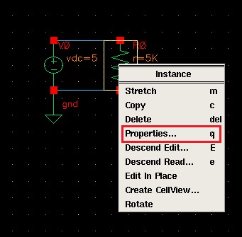
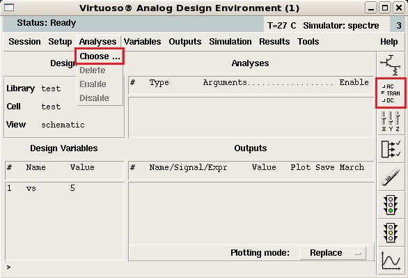
(1). 使用"滑鼠左鍵"點選電阻元件,在按"滑鼠中鍵",選擇"Properties..."。
(2).
在Edit Object Properties視窗中,在Resistance欄中將電阻值由"5K"改成"1K"後,按"OK"。
(3). 使用"滑鼠左鍵"點選電壓源元件,在按"滑鼠中鍵",選擇"Properties..."。
(4).
Edit Object Properties視窗中,在DC voltage欄將"5V"改成"vs"後,按"OK"。
(5).
Schematic Editing視窗下,選擇"Design > Check and Save"或是"Check and Save"ICON。
(6). 選擇"Tools > Analog Environment"。
(7). 在Analog Design Environment視窗,選擇"Variables > Copy From Cellview"。
(8). 在Design Variables欄中的Name會增加"vs"欄位,使用"滑鼠左鍵"點選此欄位,在選擇"Variables > Edit..."或點選
Edit Variables
"ICON。
(9). 在Value(Expr)欄位中輸入"5",後按"OK"。
(10). 選擇"Analyses > Choose"或點選"Choose Analyses"ICON。
(11). 依下圖勾選與輸入,Analysis勾選:"dc",
勾選"Save DC Operating Point",
Sweep Variable欄中勾選"Design Variable",Variable Name輸入"vs",
Sweep Range欄中,Start欄位輸入"1",Stop欄位輸入"5",Sweep Type選擇"Linear",勾選的Step Size欄位輸入"1",
完成後按"OK"。
(12). 選擇"Outputs > Save All..."存檔設定。
(13). 在Save Options視窗中,
Select signals to output(save)勾選"all",
Select power signals to output(pwr)勾選"all",
Select device currents(currents)勾選"all",
Select AC terminal currents(useprobes)勾選"yes",
設定完成按"OK"。
(14). 選擇"Simulation > Netlist and Run"或是點選"Netlist and Run"ICON。
(15). 產生了spectre.out檔。
(16). 選擇"Results > Direct Plot > Main Form..."
(17). 在Function欄位中勾選"Current",勾選完成後直接點選
Schematic Editing視窗下的電路節點。
(18). 使用"滑鼠左鍵"點選電阻與電壓源的節點。
(19). 顯示模擬結果。


